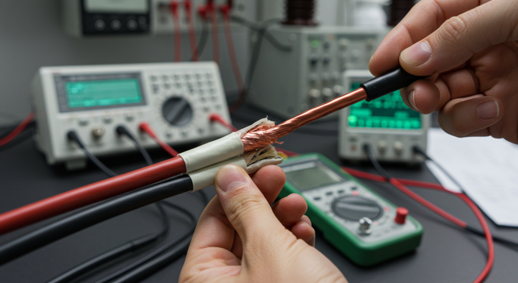
High voltage cables are the backbone of our electrical power systems, transmitting energy over long distances to keep our homes and businesses powered. However, these critical components are subject to various stresses that can lead to insulation degradation and failure if not properly maintained. Regular high voltage cable testing is essential for identifying potential issues before they result in costly outages or safety hazards. In this article, we’ll explore the different types of tests used to assess cable health and the procedures involved.
Types of High Voltage Cable Tests
Dielectric Withstand Test (Hipot Testing)
Dielectric withstand testing, also known as hipot testing, is a fundamental method for evaluating the insulation strength of high voltage cables. In this test, a voltage significantly higher than the cable’s rated voltage is applied between the conductor and the ground or shield for a specified duration. The cable’s insulation must withstand this voltage without breakdown or excessive leakage current. Hipot testing helps identify any weak spots, voids, or contamination in the insulation that could lead to premature failure under normal operating conditions.
Partial Discharge (PD) Testing
Partial discharge testing is a sensitive technique used to detect localized electrical discharges within the cable insulation. These discharges, which do not bridge the entire insulation gap, can gradually erode the insulation material and lead to eventual failure if left unchecked. PD testing can be performed both offline (with the cable de-energized) and online (with the cable in service). Offline PD testing involves applying a high voltage to the cable and measuring the discharge activity using specialized sensors and instruments. Online PD testing, on the other hand, utilizes various types of sensors to detect and analyze the high-frequency current pulses generated by partial discharges during normal operation.
Insulation Resistance (IR) Testing
Insulation resistance testing measures the resistance of the cable’s insulation to direct current (DC). It is typically performed using a megohmmeter, which applies a DC voltage between the conductor and the ground or shield. The resulting insulation resistance value provides an indication of the overall health and cleanliness of the insulation. Low IR values may suggest moisture ingress, contamination, or physical damage to the insulation. IR testing is often conducted at various intervals during the cable’s life cycle, including before installation, after repairs, and as part of routine maintenance.
Dielectric Breakdown Testing
Dielectric breakdown testing is a destructive method used to determine the ultimate dielectric strength of the cable insulation. In this test, the voltage across the insulation is gradually increased until a complete breakdown occurs, resulting in a sudden increase in current flow. The voltage at which the breakdown occurs is recorded as the dielectric breakdown voltage. This test is typically performed on sample lengths of cable or on cables that have been taken out of service. The results provide valuable information about the insulation’s quality and can help establish baseline values for comparison with future tests.
Other Relevant Tests
Very Low Frequency (VLF) Withstand Testing: VLF testing involves applying a low-frequency (0.01 Hz to 1 Hz) AC voltage to the cable for an extended duration. This test is particularly useful for evaluating the condition of aged or long cable circuits, as it stresses the insulation in a manner similar to normal operating conditions while minimizing the risk of damage due to high-frequency effects.
Tan Delta (Dissipation Factor) Measurement: Tan delta testing measures the dielectric losses in the cable insulation when subjected to an AC voltage. The dissipation factor, or tan delta, is a measure of the ratio of the resistive current to the capacitive current in the insulation. Higher tan delta values indicate greater dielectric losses and may suggest deterioration or water tree formation in the insulation.
Dielectric Withstand Test (Hipot Testing) Procedure
Isolation: Before beginning the test, ensure that the cable or equipment under test is completely isolated from the rest of the electrical system and any connected loads.
Safety Zone: Establish a clearly marked safety zone around the testing area, with appropriate warning signs indicating the presence of high voltage. For voltages up to 1000V, a radius of 1.53 meters (5 feet) is often recommended.
Grounding: Connect the ground lead of the hipot tester to a reliable building ground or grounding electrode conductor.
Connections: Attach the high voltage lead of the tester to the conductor(s) being tested. For insulation testing between conductors, connect the high voltage to one conductor and ground the others. Ensure all connections are secure and properly insulated.
Voltage and Duration Setting: Turn on the hipot tester and set the required test voltage (AC or DC) and the duration of the test according to the applicable standards. A common formula for test voltage is often based on twice the operating voltage plus 1000V. The test duration is frequently one minute. For Very Low Frequency (VLF) withstand tests, refer to IEEE Standard 400.2 for specific voltage levels and durations.
Voltage Application: Gradually increase the applied voltage to the predetermined test level.
Monitoring: Maintain the test voltage for the set duration, carefully observing for any signs of insulation breakdown, such as excessive current flow, arcing, or a sudden drop in voltage. If any failure indications occur, immediately abort the test.
Voltage Reduction: After the test duration, gradually decrease the voltage back to zero.
Verification: Switch the hipot tester to a voltage measuring mode to confirm that the circuit phase conductor and the tester itself are reading zero volts before disconnecting.
Repetition: Repeat the testing process for each conductor in the cable system, ensuring that each phase is tested against ground and against every other phase.
Disconnection: Once all tests are complete, disconnect the hipot tester from the circuits being tested.
Confirmation: Before re-energizing the system, confirm that the circuits are clear and safe. Use appropriate lockout/tagout procedures to prevent accidental energization during reconnection.
Recording: Document all test readings, including the applied voltage, duration, and any observations made during the test.
Partial Discharge (PD) Testing Procedure
Offline PD Testing:
This method involves de-energizing the cable and applying a test voltage from an external high voltage source. The procedure typically includes the following steps:
Isolation: De-energize and isolate the cable from the system. Ensure all safety procedures are followed.
High Voltage Supply: Connect a high voltage power supply capable of delivering sufficient kilovolt-amperes for the length of the cable under test. The test voltage, determined by relevant cable standards, is applied between the conductors and the cable’s screen (shield).
PD Measurement: Set up a partial discharge measuring device, which typically includes an oscilloscope, indicating equipment, a high voltage voltmeter, and an amplifier.
Voltage Application: Gradually increase the voltage to an inception voltage (U1) where PD activity starts. Hold at this level for a specified period, carefully monitoring the discharge magnitude.
Voltage Increase: Further increase the voltage to an extinction voltage (U2) while continuously measuring the discharge activity.
Calibration: To ensure accurate results, calibrate the measuring system using a discharge calibrator.
Analysis: Evaluate the recorded PD data, including the inception and extinction voltages, discharge magnitudes, and patterns. Compare the results against acceptable limits for the cable type and application.
Online PD Testing:
This approach allows for PD measurements while the cable remains energized and in service. The procedure involves:
Sensor Selection: Choose appropriate sensors based on the type of PD being measured and the cable configuration.
Sensor Placement: Install the sensors at strategic locations along the cable route. For HFCTs and RFCTs, the sensors are clamped around the earth sheath of the cable to detect the high-frequency current pulses generated by PD events.
Data Acquisition: Connect the sensors to a data acquisition system capable of sampling at high frequencies (typically in the MHz range).
Monitoring: Continuously monitor the cable for PD activity over an extended period.
Data Analysis: Process the acquired PD data using specialized software to identify and characterize the discharge sources. Analysis techniques may include pattern recognition, time-of-flight calculations, and statistical methods.
Interpretation: Evaluate the analyzed PD data to determine the severity and location of any insulation defects.
Insulation Resistance (IR) Testing Procedure
De-energization and Isolation: Before beginning the test, ensure that the cable or equipment to be tested is completely de-energized and isolated from all power sources. Follow appropriate lockout/tagout procedures to prevent accidental re-energization during the test.
Cleaning: Clean the insulation surface and the cable terminals to remove any dirt, dust, or moisture that could affect the test results.
Connections: Connect the test leads of the insulation resistance tester (commonly known as a megohmmeter or “megger”) to the cable. Typically, one lead is connected to the conductor, and the other lead is connected to the insulation sheath or to ground. For shielded cables, the connections are made between the conductor and the shield.
Voltage Selection: Set the appropriate test voltage on the megohmmeter. The voltage is usually chosen based on the rated voltage of the cable. For cables rated 1 kV and above, a 2500 V megohmmeter is often used, while for cables rated below 1 kV, a 1000 V megohmmeter may be sufficient.
Voltage Application and Reading: Apply the selected test voltage for a specific duration, typically one minute, and record the insulation resistance reading displayed by the megohmmeter. The one-minute reading is a standard benchmark for comparing IR values over time. Some tests may require longer durations, such as ten minutes, to calculate diagnostic parameters like the Polarization Index (PI) or the Dielectric Absorption Ratio (DAR). These ratios compare IR values at different times to assess the insulation’s ability to polarize and its overall condition.
Discharge: After completing the test, allow sufficient time for the cable to fully discharge any stored capacitive charge.
Recording: Document the test details, including the equipment identification, test voltage, duration, measured insulation resistance value, and the ambient temperature and humidity conditions during the test. IR values are temperature-dependent, so recording the temperature allows for standardized comparisons.
We use cookies to enhance your browsing experience, serve personalised ads or content, and analyse our traffic. By clicking "Accept All", you consent to our use of cookies.