
Description
General description :

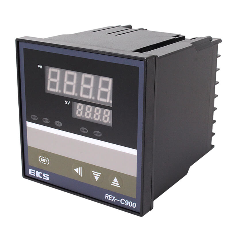
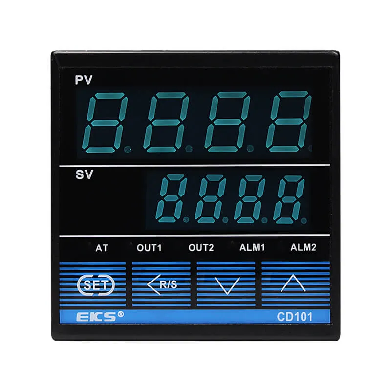
CD series intelligent (temperature) display regulator adopts 8-bit single-chip
high reliability, a variety of sensors freely input, and it adopts a wide range of
switching power supply. The product’s performance indicators, input style, control
function and the installation size are fully compatible with the i mported intelligent
digital temperature controller. CD series intelligent meters, having the latest fuzzy
control and combining with advanced PID adjustment algorithm, precisely control
the controlled objects.
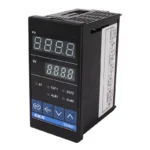
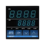
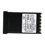
Size options:
Models | External size (W x H x D) | Hole size |
CD101 □□□-□□*□□-□ | 48x48x80 (mm) | 45 x 45 (mm) |
CD401 □□□-□□*□□-□ | 48x96x75 (mm) | 45 x 92 (mm) |
CD701 □□□-□□*□□-□ | 72x72x75 (mm) | 68 x 68 (mm) |
CD901 □□□-□□*□□-□ | 96x96x75 (mm) | 92 x 92 (mm) |
Remarks: the symbol ”□” represents what functions you need, please refer to the following explanation.
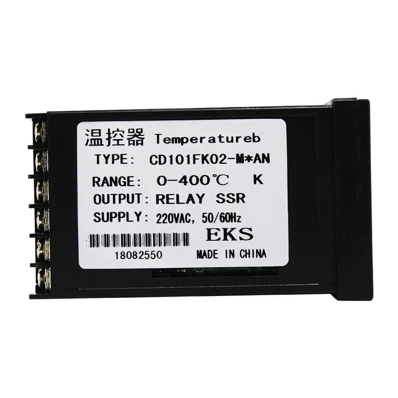
Model explanation:
CD□01 □ □ □- □ □*□ □-□
① ② ③ ④ ⑤ ⑥ ⑦ ⑧ ⑨
① Standard sizes: 1(48x48x80mm)、4(48x96x75mm)、7(72x72x75mm)、9(96x96x75mm)
② Control style:
F: PID action and automatic calculus(reverse action)
D: PID action and automatic calculus(positive action)
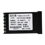
③ Input style: thermocouple: K, J, R, S, B, E, T, N, W5Re/W26Re, PLII, U, L,thermal resistance Pt100, JPt100
④ Display range:
Input type | Input display range | Code | Input type | Input display range | Code | |
K | 0~200℃ | K 01 | S | 0~1600℃ | S 01 | |
0~400℃ | K 02 | 0~1769℃ | S 02 | |||
0~600℃ | K 03 | B | 400~1800℃ | B 01 | ||
0~800℃ | K 04 | 0~1820℃ | B 02 | |||
0~1200℃ | K 06 | E | 0~800℃ | E 01 | ||
J | 0~200℃ | J 01 | 0~1000℃ | E 02 | ||
0~400℃ | J 02 | J | -199.90~+649.0℃ | D 01 | ||
0~600℃ | J 03 | -199.90~+200.0℃ | D 02 | |||
0~800℃ | J 04 | -100.0~+200.0℃ | D 05 | |||
0~1200℃ | J 06 | 0.0~+200.0℃ | D 08 | |||
R | 0~1600℃ | J 01 | 0.0~+500.0℃ | D 10 |
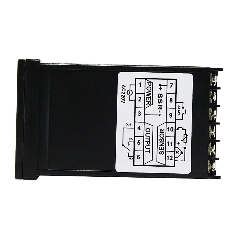
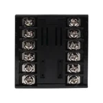
⑤ The first control output: (OUT1)(Heating side)
M: relay contact output 8: Current output(DC4-20mA)
V: voltage pulse output G: Thyristor control tube drive with trigger output
T: Thyristor control tube output
⑥ The second control output: (OUT2)(Cooling side)*2
No mark: when the control action is F or C
M: relay contact output 8: Current output(DC4-20mA)
V: voltage pulse output T: Thyristor control tube output
⑦ First alarm(ALAM1)
N: no alarm A: Upper limit deviation alarm
B: Lower limit deviation alarm C: Upper and lower limit deviation alarm
W: Lower-limit set alarm value H: Upper limit output value alarm
⑧ Second alarm(ALAM)*2(Same content as the frist alarm)
J: Lower output value alarm V: Upper set value alarm
⑨ Communication function:
N: no communication function 5: RS-485(double cable system)